Introduction
| The Cambridge Multi Pass Rheometer (MPR) is a novel dual piston capillary rheometer that can be used to investigate the rheological behaviour of melts, liquids and soft solids. It consists of two servo hydraulically controlled pistons enclosed within temperature controlled barrels and a central test section. The pistons can be moved back and forth to drive the material contained within the MPR through the test section (see the schematic diagram to the right). The speed of the pistons can be varied from 0.05mm.s-1 to 200mm.s-1, allowing very high shear rates to be generated. |
The advantages of the MPR
The unique geometry of the MPR gives it several advantages over conventional rheometers.
- Small samples size
The limited volume of the MPR barrels means that only a small amount of sample is required. As little as 10g is needed to fill the barrels and a simple capillary test section. This makes it possible to investigate the behaviour of materials that are either expensive to produce or that are only available in small amounts. - Pressurisation of sample
The pistons of the MPR can be moved together to pressurise the sample, allowing tests to be conducted above ambient pressure. - High shear rates
The high piston speeds achievable allow samples to be subjected to very high shear rates. Wall shear rates of upto 160,000s-1 can be applied to samples depending on the geometery selected. - Displacement and pressure control
In normal operation the displacement of the pistons is varied and the resulting pressure change is measured. However, with the latest control software it is possible to fix the pressure and measure the resulting displacement variation. - Repeat measurements
Having the sample contained within the barrels of the MPR allows repeated measurements to be carried out. This allows the change of material properties with time to be investigated.
Optical measurements
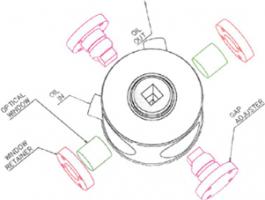
A variety of test sections can be used with the MPR from simple capillaries for determining the rheological parameters of the material under test to zig-zag channels used in conjunction with quartz windows to allow flow visualisation studies to be carried out. Any type of channel can be made for the MPR within the limits of manufacturing engineering. This technique utilises a specially designed optical test module. Metal inserts are slotted into the test module to form the slit through which the sample will flow. Stress-free quartz windows are then inserted at right angles, allowing the flow to be observed. This module has been extensively used to carry out flow birefringence studies of polymer melts.
| |
|
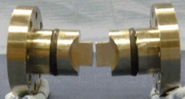
| Diagram showing the different components of the optical test module | Photograph of a pair of optical module inserts |
|
|
|
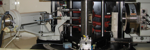
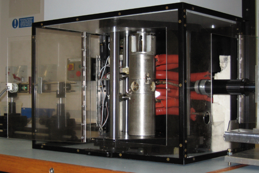
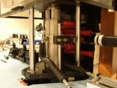
Close up picture of MPR4 set up for optical birefringence measurements. |
Optical Birefringence generates a 'contour map' of stresses observed by taking advantage of the optical anisotropy of polymers under stress. To obtain an optical birefringence pattern, the flowing sample is illuminated with monochromatic light. A polariser and analyser, placed at 90° to each other before and after the sample, ensure that a "dark field" is obtained when the sample is unstressed (i.e. at rest).
| |
| Diagram apparatus used to obtain stress birefringence patterns |
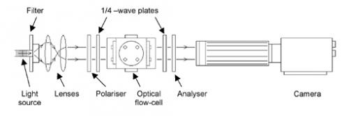
The images are recorded by the camera and saved directly to a computer. The observed birefringence patterns can then be modelled using numerical simulation software such as Polyflow or flowSolve.
|
|
|
| Photograph of the optical apparatus set up on MPR4 | The optical brirefringence pattern obtained from high density polyethylene flowing in the steady state through a contraction-expansion slit at 155°C. The flow direction is from bottom to top at an apparent wall shear rate of 12 s-1. The slit dimensions are: length = 1.5mm, width = 1.4mm depth = 10mm. The slit width contracts from 10mm to 1.4mm. Picture courtesy of Lino Scelsi. |

Cross-slot geometry: extensional flow
|
The extensional flow of polymers can have a very strong influence on their flow properties in the molten state. However, it is usually more difficult to characterise properties for extensional flow than for simple shear. As such, in many characterisations, extensional flow is simply overlooked. We have developed a simple apparatus to generate pure extensional flows in a controlled environment using the Multi-Pass Rheometer. It is capable of delivering precise flows through a known geometry. This special test section has been designed to generate a stagnation point using cross-slot flow. The pistons move towards and away from each other to force the polymer through a cross-slot geometry. Nitrogen pressure is applied to the side arms in order to force the polymer back into the system so that multiple experiments can be carried out on the same sample. The flow through the cross slot is controlled by pistons capable of delivering flowrates between 1 and 1,000 mm3/s. In the cross slot apparatus, this corresponds with maximum extension rates between 0.2 and 200 s-1. |
Schematic diagram of the MPR cross-slot geometry |
The resulting polymer flows can be characterised using pressure transducers inserted into the barrels of the rheometer and by observing the resulting optical birefringence patterns.
|
Photograph of MPR4 set up for a cross-slot flow experiment |
The flow birefringence pattern obtained from polydisperse polystyrene at a maximum extension rate of 4s-1 |

X-ray measurements
Another technique that has been successfully used in conjunction with the MPR is small and wide-angle X-ray scattering (SAXS and WAXS). Using a specially designed X-ray cabinet that can be placed around the MPR is possible to measure the change in the degree of crystallinity of a sample as it is sheared.
|
|
|
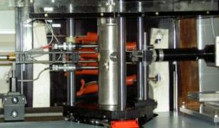
Close-up picture of MPR3 showing the barrels and mid-section in the middle |